
Shift rnicrooperations are used for serial transfer of data.The contents of a register can be shifted to the left or the right. At the same time that the bits are shifted, the first flip-flop receives its binary information from the serial input. During a shift-left operation the serial input transfers a bit into the rightmost position. During a shift-right operation the serial input transfers a bit into the leftmost position. The information transferred through the serial input determines the type of shift. There are three types of shifts: logical, circular, and arithmetic.
Logical Shift:
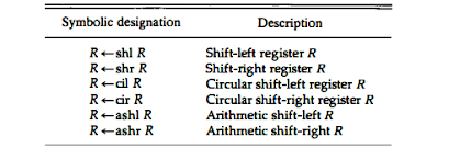
A logical shift is one that transfers 0 through the serial input. We will use the symbols shl and shr for logical shift-left and shift-right rnicrooperations. For example:R1 <- shl R1R2 <-shr R2
The two rnicrooperations that specify a 1-bit shift to the left of the content of register R 1 and a 1-bit shift to the right of the content of register R2. The register symbol must be the same on both sides of the arrow.
Circular Shif :
The circular shift (also known as a rotate operation) circulates the bits of the register around the two ends without loss of information. This is accomplished by connecting the serial output of the shift register to its serial input. We will use the symbols cil and cir for the circular shift left and right, respectively.Arithmetic Shif :
An arithmetic shift is a rnicrooperation that shifts a signed binary number to the left or right. An arithmetic shift-left multiplies a signed binary number by 2. An arithmetic shift-right divides the number by 2. Arithmetic shifts must leave the sign bit unchanged because the sign of the number remains the same when it is multiplied or divided by 2.The left bit of the register is signed bit.If sign bit is 0 then the number is positive and vice versa.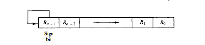
Arthimatic shift right
Shift Operations
Hardware Implementation:
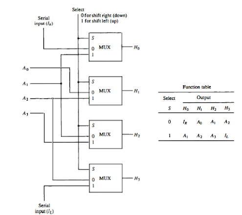
The computational shifter consist of multiplexers and one selector line and inputs as data stored in registers. The below diagram consist of 4 multiplexers and has four data inputs, A0 through A,, and four data outputs, H0 through H3• There are two serial inputs, one for shift left (IL) and the other for shift right (IR). When the selection input S = 0, the input data are shifted right (down in the diagram). When S = 1, the input data are shifted left (up in the diagram).
Shifter
A shifter with n data inputs and outputs requires n multiplexers. The two serial inputs can be controlled by another multiplexer to provide the three possible types of shifts.
0 comments :
Post a Comment
Note: only a member of this blog may post a comment.